1 Overview Huaneng Huaiyin Power Plant has two existing 200MW coal-fired generating units that were put into commercial operation in 1993 and 1994 respectively. The main auxiliary systems are composed of coal transportation, water and ash removal systems (referred to as auxiliary engine systems), and these systems and power plants are produced. The processes are closely related to each other. Their normal operation is an important condition for ensuring the stable and full production of the unit. Therefore, it is very important to perform reliable and effective monitoring of the auxiliary engine system. Before the transformation, the coal and water systems were all controlled by the PLC+ analog disk. The analog disk displayed various signals. The operating personnel controlled the automatic and manual operation of various devices by operating the hard buttons set on the operation console. Poor capacity, aging control equipment, high failure rate, spare parts are not easy to purchase; Ash removal system uses AB's Controllogix system, PLC + host computer mode. Each of the above auxiliary systems independently constitutes a set of monitoring systems, each with its own control room and on-duty personnel. At the same time, it also controls the fuel pump room, air compressor room, HVAC room, hydrogen production station, and water vapor station. The equipment and locations are scattered and the configuration of control equipment overlaps. The monitoring means are behind, resulting in management difficulties and wastage of equipment personnel. In order to further improve the overall automation level of the unit and achieve the purpose of reducing people's efficiency and facilitating management, after the successful DCS transformation of the main control system of the two units, we have continued to implement the entire plant auxiliary control system. Corresponding DCS transformation and integration.
2 Reconstruction Schemes and System Configuration After repeated investigations and comparisons, we finally selected the XDPS-400 system produced by Xinhua to form the DCS system for the auxiliary plant of the whole plant, and divided the coal transportation, water, and ash residues into three categories according to the region to which the equipment belongs. The system first implements the DCS transformation of the two subsystems of coal transportation and water conversion. The ash residue subsystem still uses the original Controllogix (PLC+PC) control system to add capacity and improve, and finally integrates with the XDPS-400 system through the gateway. Reach data sharing and monitoring. The plant-wide auxiliary DCS system has a total of 5 operator stations with the same status, including 2 coal control rooms, 2 centralized water control rooms, and 1 DCS console in the main control room of #2 unit. Each station can realize mutual operation, and any operator station can be set as an engineering station. After the commissioning of various subsystems is completed and the operation is stable, the operator stations of the coal transportation and chemical pool control rooms can be moved one by one to the DCS console of the auxiliary engine. Under the principle of decentralized control equipment, they can finally be implemented in Unit #2. The purpose of monitoring the above three subsystems is to monitor the DCS console in the main control room. The details are as follows:
The monitoring equipment of the coal conveying subsystem after transformation includes 14 belt conveyors and its ancillary equipments, 2 coal crushers, 2 large wood removers, 4 iron removers, 8 electric three links, and rapper 16 sets, 16 unloaders, automatic sampling device, real coal check device, coal yard spray device, belt spray device, clear water pump, fuel pump, etc., I/O total points about 600 points, set up in the transmission A main station of the coal control room is composed of a remote station set up in the coal bunker. The main station and the remote station are connected by optical fiber via Ethernet communication. This kind of system structure can save a large number of control cables and reduce reconstruction. The workload can reliably solve the problem of signal interference and attenuation in long-distance communication. The main station is configured with 2 pairs of DPUs and 4 Xinhua standard cabinets; the remote station is equipped with 2 Xinhua standard cabinets. Connected directly to the network communication port on the DPU station of the XDPS-400 system to achieve dual-item communication; all switch I/O points are isolated by relays; no buttons, meters, and buttons are provided on the operator's station except for the emergency stop button. Alarm light plate, the operating personnel through the CRT and mouse to achieve the monitoring of the system equipment.
After the transformation, the monitoring targets for the water purification subsystem include: water system, wastewater, hydrogen production, domestic fire-fighting water, steam station, air compressor, diesel engine, water cooling unit, raw water heating, and heating system equipment. The total number of I/O points is about 900 points. According to geographical division, set up a main station and two remote stations. The main station is located in the raw water centralized control room, equipped with 2 pairs of DPUs and 3 Xinhua standard cabinets; one remote station is set in the chemical instrument maintenance room of the steam station, and 2 standard Xinhua company cabinets are installed, and the other remote station is set in the HVAC room. In the control room, one Xinhua standard cabinet is configured, and the network communication ports on the two pairs of DPU stations of the subsystem are directly connected with the coaxial cable to realize two-way communication; all the electrical switch input points are relay-isolated.
In addition, a system server is also configured in the DCS control room of the Auxiliary Engine to collect real-time data of the DCS system and send it to the plant MIS system as required.
During the configuration of the auxiliary DCS system, the dispersion and redundancy are fully considered. The entire DCS system is configured as two major subsystems for coal transportation and water purification according to the system and geographical location of the equipment, and the remote I/O station uses Ethernet. The transmission mode realizes a "seamless" connection with the corresponding DPU, which greatly saves engineering costs and workload; optical cables are used between the two subsystems and the control room of the auxiliary engine to realize integration of monitoring and control of resource data sharing between systems; The machine interface considers the hot spares to be the same configuration. Any operator station can be set as an engineer station. It adopts the graphical configuration under full WINDOWSNT, what you see is what you get, and has the virtual DPU function; it can directly accept AC signals (100VAC , 5A) dedicated terminal board, so that some motor current and voltage signals directly into the DCS system through the transformer, eliminating the need for a considerable transmitter, saving the cost of the project. The system configuration is shown in the figure below: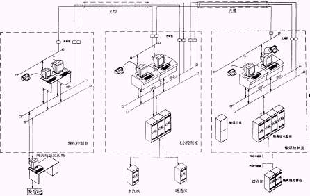
3 Project Features and Renovation Contents One of the main features of this transformation is that in the form of the project, Xinhua Company has strengthened cooperation with users (Huain Huaiyin Power Plant) to give full play to their advantages, division of labor and collaboration, and common completion. The specific division of labor is: Xinhua is responsible for the network design and hardware configuration of the entire auxiliary DCS system and provides comprehensive technical support; Huaneng Huaiyin Power Plant is responsible for the overall user software configuration (including screen configuration and logic configuration) of the system and the system Commissioning work. The other major feature is that in the form of implementation, under the premise of ensuring that the auxiliary systems can function normally at any time, the transformation of the new system will be implemented, while the construction, debugging, side-by-side operation will be carried out, and eventually all the field devices will be transferred from the old control system to the new ones. Steady transfer of the control system and achieve the desired control requirements.
The main contents of the transformation work are: the installation of new equipment cabinets (stations) for the coal and water systems, the laying and wiring of corresponding cables, the dismantling of old cabinets (sets), and the configuration and commissioning of control systems.
4 Functional characteristics of the system 4.1 Coal Handling Subsystem 4.1.1 Control Method The control mode of the coal conveyor belt is divided into three types: automatic, interlocking manual, and unlocking manual. No matter what kind of control method is adopted, when the software system captures the system fault, If the coal falls into the coal cylinder and the belt is seriously deviated, it can control the interlocking trip of the equipment.
Automatic mode is based on the production scheduling requirements, in the device flow selection menu in advance set a variety of commonly used operating modes, through the operator station keyboard and mouse operation directly select start. Interlocking Manually After the operator station has selected the operation flow, the operator starts (stops) the device one-on-one with the keyboard or mouse in the activation sequence. In this case, the interlock (locking) logic between the devices is valid. Unlocking Manually starts (stops) the device on the operator station with a keyboard or mouse without any interlock (latch). This method is only used as a maintenance test and is not used normally.
4.1.2 Process selection system According to the direction of coal flow, the coal transportation will be artificially divided into upper coal (terminal→coal), coal (coal→coal), coal (harbor, coal yard→coal), and coal ( Terminals→Bunkers) There are four types of 20 processes, which correspond to the selection window of the four types of processes. If you click on the "Steam" button in the shortcut button area, the CRT window can be switched to the following on-coal process selection screen.
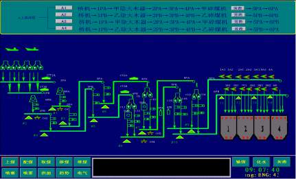 Similarly, click the "take coal", "blend coal", "pile coal" button in the shortcut button area, then the CRT activity window can be switched to the corresponding process selection screen.
Each process uses the list number to display all the coal conveying processes and the equipment used for the corresponding coal transmission type. The “process number†corresponding to each process is a switching button that enters the process. If the button is gray, it means This process cannot be selected because its combined device conflicts with other selected processes. If the button displays green, it indicates that the process is optional. Click this button to enter the process monitoring screen corresponding to the process number. The "bypass" buttons of the A and B crushers in the process equipment list are a check button. When not selected, the button displays green, indicating that the corresponding crusher in the selected process has not been bypassed and participates in the process operation; Clicking on the selected button displays a red color indicating that the corresponding crusher in the selected process does not participate in the process run and the coal flow bypasses the bypass.
4.1.3 Process Control The operation personnel can directly click the process number in the corresponding process selection screen to select the required operation process according to the production scheduling requirements. After entering the process monitoring screen corresponding to a certain process number, click the "check" button of the process, then the process indicator will show red, indicating that the process corresponding to the process number has been selected; click the process "exit" button, the process indicates Reverting to green indicates that the process corresponding to the process number has not been selected. Click the "Flow Control" button, the screen pops up the control panel of the selected process, as shown below: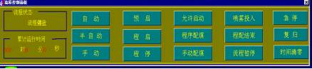
"Process status" reflects whether the selected process is running;
"Accumulative run time" reflects the run time from start to stop of the process;
The control mode of the flow is divided into three types: automatic, semi-automatic (interlocking manual) and manual (unlocking manual). The selection can be determined by clicking the corresponding button, and the button corresponding to the selected control mode turns red. Regardless of the control method selected, the real-time detection and troubleshooting functions of the software system are effective. When the software system captures a system fault, such as the coal falling in the coal cylinder, the belt is seriously deviated, slipped, and there is a pull rope and emergency stop signal. , can control the equipment interlock trip.
Click the "Pre-start" button, the selected process equipment will sound an alarm along the line, and the corresponding three-way baffle will be automatically adjusted to the selected position. In the "procedural coal blending" mode, the corresponding lower plow coal hopper will automatically fall down. Plough coal lifter. In the "automatic" mode, if the selected process satisfies the following five conditions, that is: each device has no "overhaul/local control" status (this status is the actual status of the specific equipment, the corresponding equipment on the CRT (Set on the operation panel), each device is allowed to start (no protection trip command and the belt power switch has been closed), the coal falling tube involved in the process has no coal stop signal (the coal stop signal is automatically started in the corresponding rapping After the signal has not disappeared after 20 seconds), the three-way baffles involved in the process are properly in place, and all the plow coal burners are not stuck. Then, after the "Pre-Start" button is clicked for 20 seconds, the "Enable Start" light is on, and the operator can Click the "Cheng Kai" button to start the process. The equipment along the line starts from the end of the belt conveyor and starts in reverse order with the flow direction of the reversed flow in the selected process. If all the above five conditions are not met, the "Enable Start" light will not turn on after clicking the "Pre-Start" button for 20 seconds. Even "Cheng Kai" will not respond. The operating personnel can enter the operation panel of the corresponding device on the CRT according to the actual situation, and set “shield†(artificial short-circuit) operation on the relevant signal to meet the condition of “permission to start†of the process.
Click the "Stop" button, the operation flow stops from the coal source equipment according to the direction of the coal flow, and stops the field equipment one by one in the order of a predetermined time delay. After the sequential coal blending is completed, the shutdown is automatically performed according to this program. During the operation of the process, when a device malfunctions or accidents, such as on-site pulling ropes, running deviations of more than 2 seconds, slipping or coal blocking, the accidental equipment shall be immediately stopped, and all equipment in the direction of the counter coal flow shall be jumped simultaneously. The coal crusher does not participate in the jump except for its own accident. Click the "emergency stop" button, all running equipment will immediately stop running (stopping the coal crusher).
In the "semi-automatic" control mode, the operator can start the equipment one-on-one in the direction of the anti-coal flow on the CRT, select the process through the corresponding panel, and stop the equipment one-on-one in the direction of the coal flow. It is also possible to shut down any equipment that is in operation at the site, and the equipment and all equipment in the direction of the counter coal flow will immediately be interlocked and shut down. To prevent erroneous operation, the start-up of the device still needs to satisfy the start condition in the "automatic" mode. When the start condition is not satisfied, the internal interlock should prevent any device from starting.
"Manual" control means that the operator starts and stops the device on the CRT one-on-one through the single operation panel of the corresponding device without any interlock. This method is only used for inspection and debugging and is not used normally.
Each on-site equipment controlled by the site can be controlled on-site to release the DCS and start and stop operations on site. In the local control, there is no interlocking relationship between the devices, but the CRT can display the relevant signals.
The iron remover, dust remover, and automatic sampling device start up when the corresponding belt is started and stop operation when the belt is stopped. When the “spray injection†button is pressed, the spray electromagnetic force is automatically turned on with the start of the corresponding belt.
4.1.4 Coal bunker coal blending selection and control Click on the "Coal blending" button in the shortcut button area, the upper active window is switched to the coal bunker coal blending choice and control window. The screen format is as follows.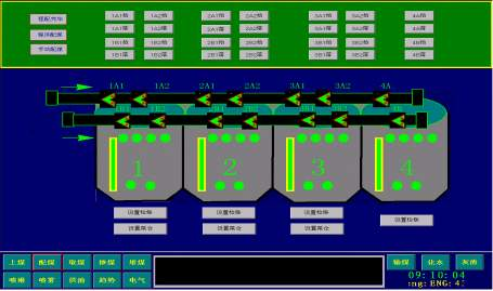
Blending coal has two kinds of control methods of program coal blending and manual coal blending. It can be selected by the two buttons of “Procedure Coal Blending†and “Manual Coal Blending†on the operation panel of each process. Click to select, the color of the button turns red, in this screen The corresponding indicator also turns red. Among them, "procedural coal blending" must be selected under the "automatic" control mode.
"Process coal blending" has three methods: low coal rank priority allocation, sequential allocation and surplus coal allocation. Under the "procedural coal blending" method, the tailing plow coal hopper is automatically dropped when the process is "pre-started," and the remaining plow coal lifters are automatically lifted. After the coal bunker belt is started, the coal bunker with a low coal level alarm is first dispatched with a certain amount of coal in order to eliminate the low coal level alarm signal; after that, all coal bunkers are filled into a full warehouse from the first bunker in order (high Coal level). If there is a low coal level in a coal bunker during the sequential coal blending, the control program immediately transfers to the coal bunker for priority coal blending until the coal bunker low coal level signal disappears and then jumps back to the original place for sequential coal blending. In the process of sequential coal blending, if high coal level or overhauling positions are encountered, it will automatically cross until the tailings are allocated to the high coal level and a "process completion" signal is issued. At this time, the coal (coal blending) process will be from the coal source equipment. Starting the shutdown, all the remaining coal will enter the tailings during the delay shutdown until the coal bunker belt stops.
When the "manual coal blending" method is used, the operator can only operate the panel through the plowing coal operator according to the coal storage condition displayed in the coal bin, and one-on-one operation of lifting and falling of the ploughing device is performed.
The operator can also set (define) the "tail storehouse" and "recovery storehouse" for each coal bunker through various setting buttons on this screen as needed.
4.1.5 Equipment status and control Click the icon of the corresponding equipment in the simulation diagram in the main window of coal transmission or each process selection window, the control panel of the equipment will pop up, and the equipment status is set in the "Status/Control" area. Indication, start and stop control buttons, etc., the button itself has a color change and is triggered by a feedback signal. "Signal/shield" area is provided with signal indications such as equipment interlock protection. The operator can perform "shielding" (make an interlock signal inoperative) to these signals according to the actual situation. "Shield" is a check. Button, change color when selected.
4.1.6 Coal Field Spray Click the "Spray" button in the shortcut button area, then the CRT activity window will be switched to the coal mine spray monitoring window.
In this screen, the monitoring of the three flushing pumps and the coal field showers can be realized.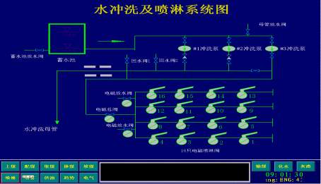
The coal field spray control is divided into two modes: "manual" and "automatic", and the selection is determined by the button on the screen.
First, "manual" control mode Select "manual" control mode, click on the appropriate spray electromagnetic cutting can pop up its control panel, by operating the control panel "on", "off" button, you can achieve a spray electromagnetic cutting On/Off control of one.
Second, the "automatic" control mode Select "automatic" control mode, you can pop up the appropriate control panel, the automatic control panel has the following three combinations of operating modes to choose from:
1. Press the shower valve serial number, ie 1→2→3→4→5→6→7→8→9→10→11→12→13→14→15→16.
2. The two spray valves are a group, in the order of 1,3→2, 4→5, 9→6, 10→7, 11→8, 12→13, 15→14, 16 Shower.
3, according to the set of groups, that is 1,2,3,4,5,9,6,10,7,11,8,12,13,14,15,16 in order, followed by valve spray.
A single set of spraying time for each of the above combinations is available in 2 minutes and 3 minutes, and the number of cycles can be selected from 1 to 4 times.
Press the "Start" button, you can press the above options and settings to achieve automatic spray, running at any time by pressing the "Stop" button to achieve automatic spray stop.
The conditions for automatic sprinkler start are: total discharge valve is in "OFF" position, spray total valve is in "ON" position, flushing pump is running, and spraying time and cycle times have been set.
4.1.7 Belt spray Click the "Spray" button in the shortcut button area, the CRT active window is switched to belt spray system.
In the above screen, the water spray electromagnetic cutting control button, the red indicates that the electromagnetic cutting has been charged open, the corresponding spray group is in the spray state; green indicates that the electromagnetic cutting power loss is closed, and the corresponding spray group is in the unsprayed state. Click the water spray electromagnetic cutting button to realize the on/off control of the corresponding electromagnetic cutting, that is: the original open (red), click to close (green); the original closed (green), click to open (red). When the water spray electric main valve is open, click the "water spray input" button in the screen, the button will turn red, and the corresponding water spray electromagnetic cut will open with the corresponding belt conveyor running, stop and close, realize automatic spray .
When the electromagnetic blow of any of the #5 belt head or #6 belt water spray group is turned on, the booster pump is connected; when all of the above electromagnetic blows are closed, the joint stop occurs.
When the dust concentration probe detects that the dust concentration exceeds the standard, the corresponding spray solenoid valve is interlocked until the dust concentration drops to the standard and the spray stops.
4.1.8 Fuel Supply System Click the "Fuel" button in the shortcut button area to switch the CRT active window to the fuel supply system.
The modified #1, #2, and #3 oil supply pump control logic is implemented in the coal conveying DCS system. Through this window, remote start, stop, interlock and other logic control of the three oil supply pumps can be realized. The local control loop is simplified. It can be manually started/stopped. Each fuel pump is set to "work", "hot standby", "cold standby" three states.
When the fuel supply pump is in the "work" state, click on its "start" or "stop" button to achieve remote start/stop operation of the pump;
When the fuel supply pump is in the "hot standby" state, once the operating pump is tripped in the working state, the pump is immediately put into operation to achieve continuous oil supply. When one pump is running, two sets of oil supply pumps cannot be set as "hot spare" at the same time. status;
The "cold preparation" status is an empty position. When the fuel supply pump is in the "cold standby" status, the pump is equivalent to the withdrawal control, and neither the start/stop operation can be performed manually on the screen, nor can the interlock be activated when the operation pump is tripped.
Through this window, you can also monitor the operating status and related parameters of the three pumps. These parameters mainly include: #1, #2, #3 supply pump current, oil supply pressure, temperature, flow, #1, #2 tank oil level, oil temperature, heating steam pressure, temperature.
4.1.9 Optical plate alarm Click the "Alarm" button in the shortcut button area, then the upper active window will be switched to the optical plate alarm monitoring window (page viewable). The alarm content of each optical plate is omitted.
4.2 Chemical Subsystem 4.2.1 Control Contents and Requirements There are three control modes: program-controlled automatic, soft-operated remote control, and local manual. No matter what type of control is adopted, the feedback of controlled objects (such as valves and pumps) is Consistent.
4.2.1.1 Water production systems include pretreatment systems, primary desalination systems, secondary desalination systems, and industrial wastewater treatment systems.
Pretreatment program control includes start and stop of clarifier, automatic dosing, automatic blowdown, start and stop of mechanical filter, automatic backwash, and increase raw water heating at the same time, adjust raw steam inlet temperature according to the raw water inlet temperature. The amount of raw water is finally controlled at the set temperature.
The desalination system includes 2 clear water pumps, 3 mechanical filters, 2 sets of primary desalination systems, 2 sets of mixed beds, 2 desalting tanks, and related reclaimed (or backwashing) equipment, among which mechanical filters, 1 The desalination system and mixed bed can be divided into four states: washing, operation, regeneration (or backwashing), and shutdown. When the desalination tanks are at high level, the entire desalination system is stopped; when the desalination tanks are at low level, the computer prompts whether to put the desalination system (one or two sets) into operation. The desalting system program control increases the regeneration and operation of the mixed bed on the basis of the first stage salt removal. In addition to salt water to achieve remote operation, the replenishment flow rate will automatically calculate the replenishment rate.
First, the control of a desalination system 1, the first desalination system program control regeneration when the y = ≥ ≥ 5.0us/cm yin water effluent when the first set of de-salting system is judged invalid, then stop the set of desalination of the first set of desalination System and synchronous operation of mixed bed inlet and outlet gates. Corresponding filtration system (filter inlet and outlet door) and clear water pump stop operation at the same time 2. Program controlled operation of first-stage desalination system, outage selection of clear water pump, one set of filter, first desalination system, mixed bed, from filtration The washing process is started, the first stage salt removal system is being washed, the mixed bed is being washed until all the steps are being washed and passed, and the shutdown is started from the mixed bed, and the secondary and secondary desalting systems are gradually stopped ( Mixed bed control, automatic switching and regeneration of mixed bed (limited to one mixed bed operation)
When the operating time of the mixed bed reaches one month or the mixed bed is given “overhaulâ€, the computer will alarm and prompt to change the bed. After confirmation, another standby mixed bed is performed and the computer is prompted to change to When it is put into operation, the failed mixed bed will be shut down and the mixed bed will be regenerated.
2. Automatic regeneration of mixed beds (limited to the operation of two mixed beds)
When the operating time of the mixed bed reaches one month or the mixed bed is given “overhaulâ€, the computer will alarm and pop up the number of a de-salting system that is out of service (including stopping a clear water pump, filters and a set of primary Salt system), (numbered as default, modifiable), followed by the failed mixed bed, confirming that the computer prompts regeneration of the failed mixed bed. After the regeneration is over, the computer will prompt the desalination system that was just put into operation.
Industrial waste water system: When the water level in a neutralization tank is at a high water level, the pH of the water in the tank is adjusted, and after discharge, the waste pump is activated.
4.2.1.2 Automatic Control of Water Vapor The water vapor automatic control includes a water vapor station data acquisition system, a desalination cooling water system, and an automatic dosing system.
The water vapor data acquisition system includes various water vapor samples of the steam station, cold water in the field, and other data, and collects data. With data processing, analysis and statistics functions, and has expert diagnostic functions.
The desalting cooling water system realizes remote operation, realizes the interlocking of the desalination circulating pump, and achieves the function of desalinating cooling water and water cut protection.
Furnace auto-dosing includes phosphate, ammonia, hydrazine dosing, remote dispensing and automatic dispensing.
4.2.1.3 Hydrogen Production System Control At the same time of realizing the remote display of the #1 and #2 hydrogen production systems and the #2 system drying equipment, the hydrogen protection system protection function and remote operation under the silicon rectification accident are realized.
4.2.1.4 Living fire-fighting water system realizes remote operation and display, and realizes automatic start and stop, operation and backwash of the water making system after automatic dosing and transformation. Realize remote operation and electrical interlocking and pressure interlocking of high and low pressure fire-fighting pumps and industrial pumps. 4.2.1.5 Other other control devices include three 400V air compressors, two air-conditioning chillers, one diesel generator set and HVAC system. Requires remote operation of these devices, parameter display, over-limit alarm and interlock start-stop.
4.2.2 Monitoring screen setup The system monitoring simulation diagram is 25 pictures, and the shortcut button has reached 7 pictures. The call relationship of the picture is as follows:
Main control of water, water treatment room, waste water pool, life fire pump room, hydrogen production station, steam station, HVAC room, 400V air compressor room, water treatment room, water treatment overview, raw water, clarification system, water and filtration System #1 Desalting System · #2 Desalting System · Mixed Bed and Desalting Parent Pipe System · Acid and Alkali Metering System · Acid and Alkaline Storage System · Water System for Water System Waste Water Pool · Wastewater Treatment System Life Fire Pump Room · Life Fire Pump System Hydrogen Production Station • #1 Hydrogen Production System • #2 Hydrogen Production System • #2 Drying Plant • Hydrogen Storage System Water Vapor Plant • Vapor Sampling System • Desalination Cooling Water System • Furnace Water Phosphate Dosing System • Condensate Ammonia addition system · Feedwater ammonia treatment system HVAC room · Water cooling unit · Heating system 400V air compressor room · 400V air compressor unit · Raw water heating system · Diesel engine group shortcut button Arrival screen · Programmable control main screen · Interlock cut Screen/alarm light card screen/parameter manual input screen/group display screen/trend display screen/report display screen 5 System commissioning and commissioning status Due to Xinhua Company's configuration of system hardware and configuration of system software by power plant technicians, etc. The preparatory work was solid and prepared Points, thoughtful, plus Xinhua companies in the implementation of the whole project in a timely and strong technical support, making XDPS-400 Auxiliary DCS system reform has been in good running condition. This is very important, because during the renovation, especially the transformation of the coal conveying system, in order to ensure the smooth delivery of the system equipment, ready to use at any time, does not affect the safe and stable operation of the unit, and the construction has broken the procedure for the system to be powered on after the wiring is installed first. However, after the control cabinet, system power supply, and network connection are installed, they are powered on and the DCS system is always in a good state of operation to ensure that each device can be monitored normally after it is moved to the DCS system. In fact, we have completely done this, which also proves from practice that the XDPS-400 system is a very stable and reliable and advanced control system with low hardware failure rate, friendly software interface, convenient configuration and debugging, and easy operation.
At present, all the coal handling subsystems have been commissioned, the old control system has been completely dismantled, the new DCS system and equipment monitoring are normal, and the coal handling processes can be put into programmed operation. The monitoring of other systems and equipment can also meet the expected requirements. The water system has completed the commissioning of some of the equipment. The original program-controlled cabinet of the water system has been removed. The CRT of the new DCS system has a single operation and signal feedback is normal, and the water program control is being debugged.
6 transformation experience through this transformation has the following experience:
First, it is proved in practice that the XDPS-400 system is indeed a set of very stable and reliable and advanced control systems, with low hardware failure rate, friendly software interface, convenient configuration and debugging, and easy operation.
The second is that in this transformation, the technical personnel of the power plant undertook all the screen and logic configuration and system debugging of the DCS system. This not only exerted its expertise, made the monitoring program more practical and effective, but also tempered its own team. This will create conditions for future system modifications and improvements, and even further cooperation with Xinhua.
Thirdly, the selection of products from US NI companies for remote I/O stations is not necessarily the best. Because of the limited understanding of this type of card, NI card damage and abnormal analog transmission have occurred during debugging, and spare parts are not Like Xinhua Cards comes so easily. In fact, the remote I/O station developed by Xinhua is worth a try.
2 Reconstruction Schemes and System Configuration After repeated investigations and comparisons, we finally selected the XDPS-400 system produced by Xinhua to form the DCS system for the auxiliary plant of the whole plant, and divided the coal transportation, water, and ash residues into three categories according to the region to which the equipment belongs. The system first implements the DCS transformation of the two subsystems of coal transportation and water conversion. The ash residue subsystem still uses the original Controllogix (PLC+PC) control system to add capacity and improve, and finally integrates with the XDPS-400 system through the gateway. Reach data sharing and monitoring. The plant-wide auxiliary DCS system has a total of 5 operator stations with the same status, including 2 coal control rooms, 2 centralized water control rooms, and 1 DCS console in the main control room of #2 unit. Each station can realize mutual operation, and any operator station can be set as an engineering station. After the commissioning of various subsystems is completed and the operation is stable, the operator stations of the coal transportation and chemical pool control rooms can be moved one by one to the DCS console of the auxiliary engine. Under the principle of decentralized control equipment, they can finally be implemented in Unit #2. The purpose of monitoring the above three subsystems is to monitor the DCS console in the main control room. The details are as follows:
The monitoring equipment of the coal conveying subsystem after transformation includes 14 belt conveyors and its ancillary equipments, 2 coal crushers, 2 large wood removers, 4 iron removers, 8 electric three links, and rapper 16 sets, 16 unloaders, automatic sampling device, real coal check device, coal yard spray device, belt spray device, clear water pump, fuel pump, etc., I/O total points about 600 points, set up in the transmission A main station of the coal control room is composed of a remote station set up in the coal bunker. The main station and the remote station are connected by optical fiber via Ethernet communication. This kind of system structure can save a large number of control cables and reduce reconstruction. The workload can reliably solve the problem of signal interference and attenuation in long-distance communication. The main station is configured with 2 pairs of DPUs and 4 Xinhua standard cabinets; the remote station is equipped with 2 Xinhua standard cabinets. Connected directly to the network communication port on the DPU station of the XDPS-400 system to achieve dual-item communication; all switch I/O points are isolated by relays; no buttons, meters, and buttons are provided on the operator's station except for the emergency stop button. Alarm light plate, the operating personnel through the CRT and mouse to achieve the monitoring of the system equipment.
After the transformation, the monitoring targets for the water purification subsystem include: water system, wastewater, hydrogen production, domestic fire-fighting water, steam station, air compressor, diesel engine, water cooling unit, raw water heating, and heating system equipment. The total number of I/O points is about 900 points. According to geographical division, set up a main station and two remote stations. The main station is located in the raw water centralized control room, equipped with 2 pairs of DPUs and 3 Xinhua standard cabinets; one remote station is set in the chemical instrument maintenance room of the steam station, and 2 standard Xinhua company cabinets are installed, and the other remote station is set in the HVAC room. In the control room, one Xinhua standard cabinet is configured, and the network communication ports on the two pairs of DPU stations of the subsystem are directly connected with the coaxial cable to realize two-way communication; all the electrical switch input points are relay-isolated.
In addition, a system server is also configured in the DCS control room of the Auxiliary Engine to collect real-time data of the DCS system and send it to the plant MIS system as required.
During the configuration of the auxiliary DCS system, the dispersion and redundancy are fully considered. The entire DCS system is configured as two major subsystems for coal transportation and water purification according to the system and geographical location of the equipment, and the remote I/O station uses Ethernet. The transmission mode realizes a "seamless" connection with the corresponding DPU, which greatly saves engineering costs and workload; optical cables are used between the two subsystems and the control room of the auxiliary engine to realize integration of monitoring and control of resource data sharing between systems; The machine interface considers the hot spares to be the same configuration. Any operator station can be set as an engineer station. It adopts the graphical configuration under full WINDOWSNT, what you see is what you get, and has the virtual DPU function; it can directly accept AC signals (100VAC , 5A) dedicated terminal board, so that some motor current and voltage signals directly into the DCS system through the transformer, eliminating the need for a considerable transmitter, saving the cost of the project. The system configuration is shown in the figure below:
3 Project Features and Renovation Contents One of the main features of this transformation is that in the form of the project, Xinhua Company has strengthened cooperation with users (Huain Huaiyin Power Plant) to give full play to their advantages, division of labor and collaboration, and common completion. The specific division of labor is: Xinhua is responsible for the network design and hardware configuration of the entire auxiliary DCS system and provides comprehensive technical support; Huaneng Huaiyin Power Plant is responsible for the overall user software configuration (including screen configuration and logic configuration) of the system and the system Commissioning work. The other major feature is that in the form of implementation, under the premise of ensuring that the auxiliary systems can function normally at any time, the transformation of the new system will be implemented, while the construction, debugging, side-by-side operation will be carried out, and eventually all the field devices will be transferred from the old control system to the new ones. Steady transfer of the control system and achieve the desired control requirements.
The main contents of the transformation work are: the installation of new equipment cabinets (stations) for the coal and water systems, the laying and wiring of corresponding cables, the dismantling of old cabinets (sets), and the configuration and commissioning of control systems.
4 Functional characteristics of the system 4.1 Coal Handling Subsystem 4.1.1 Control Method The control mode of the coal conveyor belt is divided into three types: automatic, interlocking manual, and unlocking manual. No matter what kind of control method is adopted, when the software system captures the system fault, If the coal falls into the coal cylinder and the belt is seriously deviated, it can control the interlocking trip of the equipment.
Automatic mode is based on the production scheduling requirements, in the device flow selection menu in advance set a variety of commonly used operating modes, through the operator station keyboard and mouse operation directly select start. Interlocking Manually After the operator station has selected the operation flow, the operator starts (stops) the device one-on-one with the keyboard or mouse in the activation sequence. In this case, the interlock (locking) logic between the devices is valid. Unlocking Manually starts (stops) the device on the operator station with a keyboard or mouse without any interlock (latch). This method is only used as a maintenance test and is not used normally.
4.1.2 Process selection system According to the direction of coal flow, the coal transportation will be artificially divided into upper coal (terminal→coal), coal (coal→coal), coal (harbor, coal yard→coal), and coal ( Terminals→Bunkers) There are four types of 20 processes, which correspond to the selection window of the four types of processes. If you click on the "Steam" button in the shortcut button area, the CRT window can be switched to the following on-coal process selection screen.
Each process uses the list number to display all the coal conveying processes and the equipment used for the corresponding coal transmission type. The “process number†corresponding to each process is a switching button that enters the process. If the button is gray, it means This process cannot be selected because its combined device conflicts with other selected processes. If the button displays green, it indicates that the process is optional. Click this button to enter the process monitoring screen corresponding to the process number. The "bypass" buttons of the A and B crushers in the process equipment list are a check button. When not selected, the button displays green, indicating that the corresponding crusher in the selected process has not been bypassed and participates in the process operation; Clicking on the selected button displays a red color indicating that the corresponding crusher in the selected process does not participate in the process run and the coal flow bypasses the bypass.
4.1.3 Process Control The operation personnel can directly click the process number in the corresponding process selection screen to select the required operation process according to the production scheduling requirements. After entering the process monitoring screen corresponding to a certain process number, click the "check" button of the process, then the process indicator will show red, indicating that the process corresponding to the process number has been selected; click the process "exit" button, the process indicates Reverting to green indicates that the process corresponding to the process number has not been selected. Click the "Flow Control" button, the screen pops up the control panel of the selected process, as shown below:
"Process status" reflects whether the selected process is running;
"Accumulative run time" reflects the run time from start to stop of the process;
The control mode of the flow is divided into three types: automatic, semi-automatic (interlocking manual) and manual (unlocking manual). The selection can be determined by clicking the corresponding button, and the button corresponding to the selected control mode turns red. Regardless of the control method selected, the real-time detection and troubleshooting functions of the software system are effective. When the software system captures a system fault, such as the coal falling in the coal cylinder, the belt is seriously deviated, slipped, and there is a pull rope and emergency stop signal. , can control the equipment interlock trip.
Click the "Pre-start" button, the selected process equipment will sound an alarm along the line, and the corresponding three-way baffle will be automatically adjusted to the selected position. In the "procedural coal blending" mode, the corresponding lower plow coal hopper will automatically fall down. Plough coal lifter. In the "automatic" mode, if the selected process satisfies the following five conditions, that is: each device has no "overhaul/local control" status (this status is the actual status of the specific equipment, the corresponding equipment on the CRT (Set on the operation panel), each device is allowed to start (no protection trip command and the belt power switch has been closed), the coal falling tube involved in the process has no coal stop signal (the coal stop signal is automatically started in the corresponding rapping After the signal has not disappeared after 20 seconds), the three-way baffles involved in the process are properly in place, and all the plow coal burners are not stuck. Then, after the "Pre-Start" button is clicked for 20 seconds, the "Enable Start" light is on, and the operator can Click the "Cheng Kai" button to start the process. The equipment along the line starts from the end of the belt conveyor and starts in reverse order with the flow direction of the reversed flow in the selected process. If all the above five conditions are not met, the "Enable Start" light will not turn on after clicking the "Pre-Start" button for 20 seconds. Even "Cheng Kai" will not respond. The operating personnel can enter the operation panel of the corresponding device on the CRT according to the actual situation, and set “shield†(artificial short-circuit) operation on the relevant signal to meet the condition of “permission to start†of the process.
Click the "Stop" button, the operation flow stops from the coal source equipment according to the direction of the coal flow, and stops the field equipment one by one in the order of a predetermined time delay. After the sequential coal blending is completed, the shutdown is automatically performed according to this program. During the operation of the process, when a device malfunctions or accidents, such as on-site pulling ropes, running deviations of more than 2 seconds, slipping or coal blocking, the accidental equipment shall be immediately stopped, and all equipment in the direction of the counter coal flow shall be jumped simultaneously. The coal crusher does not participate in the jump except for its own accident. Click the "emergency stop" button, all running equipment will immediately stop running (stopping the coal crusher).
In the "semi-automatic" control mode, the operator can start the equipment one-on-one in the direction of the anti-coal flow on the CRT, select the process through the corresponding panel, and stop the equipment one-on-one in the direction of the coal flow. It is also possible to shut down any equipment that is in operation at the site, and the equipment and all equipment in the direction of the counter coal flow will immediately be interlocked and shut down. To prevent erroneous operation, the start-up of the device still needs to satisfy the start condition in the "automatic" mode. When the start condition is not satisfied, the internal interlock should prevent any device from starting.
"Manual" control means that the operator starts and stops the device on the CRT one-on-one through the single operation panel of the corresponding device without any interlock. This method is only used for inspection and debugging and is not used normally.
Each on-site equipment controlled by the site can be controlled on-site to release the DCS and start and stop operations on site. In the local control, there is no interlocking relationship between the devices, but the CRT can display the relevant signals.
The iron remover, dust remover, and automatic sampling device start up when the corresponding belt is started and stop operation when the belt is stopped. When the “spray injection†button is pressed, the spray electromagnetic force is automatically turned on with the start of the corresponding belt.
4.1.4 Coal bunker coal blending selection and control Click on the "Coal blending" button in the shortcut button area, the upper active window is switched to the coal bunker coal blending choice and control window. The screen format is as follows.
Blending coal has two kinds of control methods of program coal blending and manual coal blending. It can be selected by the two buttons of “Procedure Coal Blending†and “Manual Coal Blending†on the operation panel of each process. Click to select, the color of the button turns red, in this screen The corresponding indicator also turns red. Among them, "procedural coal blending" must be selected under the "automatic" control mode.
"Process coal blending" has three methods: low coal rank priority allocation, sequential allocation and surplus coal allocation. Under the "procedural coal blending" method, the tailing plow coal hopper is automatically dropped when the process is "pre-started," and the remaining plow coal lifters are automatically lifted. After the coal bunker belt is started, the coal bunker with a low coal level alarm is first dispatched with a certain amount of coal in order to eliminate the low coal level alarm signal; after that, all coal bunkers are filled into a full warehouse from the first bunker in order (high Coal level). If there is a low coal level in a coal bunker during the sequential coal blending, the control program immediately transfers to the coal bunker for priority coal blending until the coal bunker low coal level signal disappears and then jumps back to the original place for sequential coal blending. In the process of sequential coal blending, if high coal level or overhauling positions are encountered, it will automatically cross until the tailings are allocated to the high coal level and a "process completion" signal is issued. At this time, the coal (coal blending) process will be from the coal source equipment. Starting the shutdown, all the remaining coal will enter the tailings during the delay shutdown until the coal bunker belt stops.
When the "manual coal blending" method is used, the operator can only operate the panel through the plowing coal operator according to the coal storage condition displayed in the coal bin, and one-on-one operation of lifting and falling of the ploughing device is performed.
The operator can also set (define) the "tail storehouse" and "recovery storehouse" for each coal bunker through various setting buttons on this screen as needed.
4.1.5 Equipment status and control Click the icon of the corresponding equipment in the simulation diagram in the main window of coal transmission or each process selection window, the control panel of the equipment will pop up, and the equipment status is set in the "Status/Control" area. Indication, start and stop control buttons, etc., the button itself has a color change and is triggered by a feedback signal. "Signal/shield" area is provided with signal indications such as equipment interlock protection. The operator can perform "shielding" (make an interlock signal inoperative) to these signals according to the actual situation. "Shield" is a check. Button, change color when selected.
4.1.6 Coal Field Spray Click the "Spray" button in the shortcut button area, then the CRT activity window will be switched to the coal mine spray monitoring window.
In this screen, the monitoring of the three flushing pumps and the coal field showers can be realized.
The coal field spray control is divided into two modes: "manual" and "automatic", and the selection is determined by the button on the screen.
First, "manual" control mode Select "manual" control mode, click on the appropriate spray electromagnetic cutting can pop up its control panel, by operating the control panel "on", "off" button, you can achieve a spray electromagnetic cutting On/Off control of one.
Second, the "automatic" control mode Select "automatic" control mode, you can pop up the appropriate control panel, the automatic control panel has the following three combinations of operating modes to choose from:
1. Press the shower valve serial number, ie 1→2→3→4→5→6→7→8→9→10→11→12→13→14→15→16.
2. The two spray valves are a group, in the order of 1,3→2, 4→5, 9→6, 10→7, 11→8, 12→13, 15→14, 16 Shower.
3, according to the set of groups, that is 1,2,3,4,5,9,6,10,7,11,8,12,13,14,15,16 in order, followed by valve spray.
A single set of spraying time for each of the above combinations is available in 2 minutes and 3 minutes, and the number of cycles can be selected from 1 to 4 times.
Press the "Start" button, you can press the above options and settings to achieve automatic spray, running at any time by pressing the "Stop" button to achieve automatic spray stop.
The conditions for automatic sprinkler start are: total discharge valve is in "OFF" position, spray total valve is in "ON" position, flushing pump is running, and spraying time and cycle times have been set.
4.1.7 Belt spray Click the "Spray" button in the shortcut button area, the CRT active window is switched to belt spray system.
In the above screen, the water spray electromagnetic cutting control button, the red indicates that the electromagnetic cutting has been charged open, the corresponding spray group is in the spray state; green indicates that the electromagnetic cutting power loss is closed, and the corresponding spray group is in the unsprayed state. Click the water spray electromagnetic cutting button to realize the on/off control of the corresponding electromagnetic cutting, that is: the original open (red), click to close (green); the original closed (green), click to open (red). When the water spray electric main valve is open, click the "water spray input" button in the screen, the button will turn red, and the corresponding water spray electromagnetic cut will open with the corresponding belt conveyor running, stop and close, realize automatic spray .
When the electromagnetic blow of any of the #5 belt head or #6 belt water spray group is turned on, the booster pump is connected; when all of the above electromagnetic blows are closed, the joint stop occurs.
When the dust concentration probe detects that the dust concentration exceeds the standard, the corresponding spray solenoid valve is interlocked until the dust concentration drops to the standard and the spray stops.
4.1.8 Fuel Supply System Click the "Fuel" button in the shortcut button area to switch the CRT active window to the fuel supply system.
The modified #1, #2, and #3 oil supply pump control logic is implemented in the coal conveying DCS system. Through this window, remote start, stop, interlock and other logic control of the three oil supply pumps can be realized. The local control loop is simplified. It can be manually started/stopped. Each fuel pump is set to "work", "hot standby", "cold standby" three states.
When the fuel supply pump is in the "work" state, click on its "start" or "stop" button to achieve remote start/stop operation of the pump;
When the fuel supply pump is in the "hot standby" state, once the operating pump is tripped in the working state, the pump is immediately put into operation to achieve continuous oil supply. When one pump is running, two sets of oil supply pumps cannot be set as "hot spare" at the same time. status;
The "cold preparation" status is an empty position. When the fuel supply pump is in the "cold standby" status, the pump is equivalent to the withdrawal control, and neither the start/stop operation can be performed manually on the screen, nor can the interlock be activated when the operation pump is tripped.
Through this window, you can also monitor the operating status and related parameters of the three pumps. These parameters mainly include: #1, #2, #3 supply pump current, oil supply pressure, temperature, flow, #1, #2 tank oil level, oil temperature, heating steam pressure, temperature.
4.1.9 Optical plate alarm Click the "Alarm" button in the shortcut button area, then the upper active window will be switched to the optical plate alarm monitoring window (page viewable). The alarm content of each optical plate is omitted.
4.2 Chemical Subsystem 4.2.1 Control Contents and Requirements There are three control modes: program-controlled automatic, soft-operated remote control, and local manual. No matter what type of control is adopted, the feedback of controlled objects (such as valves and pumps) is Consistent.
4.2.1.1 Water production systems include pretreatment systems, primary desalination systems, secondary desalination systems, and industrial wastewater treatment systems.
Pretreatment program control includes start and stop of clarifier, automatic dosing, automatic blowdown, start and stop of mechanical filter, automatic backwash, and increase raw water heating at the same time, adjust raw steam inlet temperature according to the raw water inlet temperature. The amount of raw water is finally controlled at the set temperature.
The desalination system includes 2 clear water pumps, 3 mechanical filters, 2 sets of primary desalination systems, 2 sets of mixed beds, 2 desalting tanks, and related reclaimed (or backwashing) equipment, among which mechanical filters, 1 The desalination system and mixed bed can be divided into four states: washing, operation, regeneration (or backwashing), and shutdown. When the desalination tanks are at high level, the entire desalination system is stopped; when the desalination tanks are at low level, the computer prompts whether to put the desalination system (one or two sets) into operation. The desalting system program control increases the regeneration and operation of the mixed bed on the basis of the first stage salt removal. In addition to salt water to achieve remote operation, the replenishment flow rate will automatically calculate the replenishment rate.
First, the control of a desalination system 1, the first desalination system program control regeneration when the y = ≥ ≥ 5.0us/cm yin water effluent when the first set of de-salting system is judged invalid, then stop the set of desalination of the first set of desalination System and synchronous operation of mixed bed inlet and outlet gates. Corresponding filtration system (filter inlet and outlet door) and clear water pump stop operation at the same time 2. Program controlled operation of first-stage desalination system, outage selection of clear water pump, one set of filter, first desalination system, mixed bed, from filtration The washing process is started, the first stage salt removal system is being washed, the mixed bed is being washed until all the steps are being washed and passed, and the shutdown is started from the mixed bed, and the secondary and secondary desalting systems are gradually stopped ( Mixed bed control, automatic switching and regeneration of mixed bed (limited to one mixed bed operation)
When the operating time of the mixed bed reaches one month or the mixed bed is given “overhaulâ€, the computer will alarm and prompt to change the bed. After confirmation, another standby mixed bed is performed and the computer is prompted to change to When it is put into operation, the failed mixed bed will be shut down and the mixed bed will be regenerated.
2. Automatic regeneration of mixed beds (limited to the operation of two mixed beds)
When the operating time of the mixed bed reaches one month or the mixed bed is given “overhaulâ€, the computer will alarm and pop up the number of a de-salting system that is out of service (including stopping a clear water pump, filters and a set of primary Salt system), (numbered as default, modifiable), followed by the failed mixed bed, confirming that the computer prompts regeneration of the failed mixed bed. After the regeneration is over, the computer will prompt the desalination system that was just put into operation.
Industrial waste water system: When the water level in a neutralization tank is at a high water level, the pH of the water in the tank is adjusted, and after discharge, the waste pump is activated.
4.2.1.2 Automatic Control of Water Vapor The water vapor automatic control includes a water vapor station data acquisition system, a desalination cooling water system, and an automatic dosing system.
The water vapor data acquisition system includes various water vapor samples of the steam station, cold water in the field, and other data, and collects data. With data processing, analysis and statistics functions, and has expert diagnostic functions.
The desalting cooling water system realizes remote operation, realizes the interlocking of the desalination circulating pump, and achieves the function of desalinating cooling water and water cut protection.
Furnace auto-dosing includes phosphate, ammonia, hydrazine dosing, remote dispensing and automatic dispensing.
4.2.1.3 Hydrogen Production System Control At the same time of realizing the remote display of the #1 and #2 hydrogen production systems and the #2 system drying equipment, the hydrogen protection system protection function and remote operation under the silicon rectification accident are realized.
4.2.1.4 Living fire-fighting water system realizes remote operation and display, and realizes automatic start and stop, operation and backwash of the water making system after automatic dosing and transformation. Realize remote operation and electrical interlocking and pressure interlocking of high and low pressure fire-fighting pumps and industrial pumps. 4.2.1.5 Other other control devices include three 400V air compressors, two air-conditioning chillers, one diesel generator set and HVAC system. Requires remote operation of these devices, parameter display, over-limit alarm and interlock start-stop.
4.2.2 Monitoring screen setup The system monitoring simulation diagram is 25 pictures, and the shortcut button has reached 7 pictures. The call relationship of the picture is as follows:
Main control of water, water treatment room, waste water pool, life fire pump room, hydrogen production station, steam station, HVAC room, 400V air compressor room, water treatment room, water treatment overview, raw water, clarification system, water and filtration System #1 Desalting System · #2 Desalting System · Mixed Bed and Desalting Parent Pipe System · Acid and Alkali Metering System · Acid and Alkaline Storage System · Water System for Water System Waste Water Pool · Wastewater Treatment System Life Fire Pump Room · Life Fire Pump System Hydrogen Production Station • #1 Hydrogen Production System • #2 Hydrogen Production System • #2 Drying Plant • Hydrogen Storage System Water Vapor Plant • Vapor Sampling System • Desalination Cooling Water System • Furnace Water Phosphate Dosing System • Condensate Ammonia addition system · Feedwater ammonia treatment system HVAC room · Water cooling unit · Heating system 400V air compressor room · 400V air compressor unit · Raw water heating system · Diesel engine group shortcut button Arrival screen · Programmable control main screen · Interlock cut Screen/alarm light card screen/parameter manual input screen/group display screen/trend display screen/report display screen 5 System commissioning and commissioning status Due to Xinhua Company's configuration of system hardware and configuration of system software by power plant technicians, etc. The preparatory work was solid and prepared Points, thoughtful, plus Xinhua companies in the implementation of the whole project in a timely and strong technical support, making XDPS-400 Auxiliary DCS system reform has been in good running condition. This is very important, because during the renovation, especially the transformation of the coal conveying system, in order to ensure the smooth delivery of the system equipment, ready to use at any time, does not affect the safe and stable operation of the unit, and the construction has broken the procedure for the system to be powered on after the wiring is installed first. However, after the control cabinet, system power supply, and network connection are installed, they are powered on and the DCS system is always in a good state of operation to ensure that each device can be monitored normally after it is moved to the DCS system. In fact, we have completely done this, which also proves from practice that the XDPS-400 system is a very stable and reliable and advanced control system with low hardware failure rate, friendly software interface, convenient configuration and debugging, and easy operation.
At present, all the coal handling subsystems have been commissioned, the old control system has been completely dismantled, the new DCS system and equipment monitoring are normal, and the coal handling processes can be put into programmed operation. The monitoring of other systems and equipment can also meet the expected requirements. The water system has completed the commissioning of some of the equipment. The original program-controlled cabinet of the water system has been removed. The CRT of the new DCS system has a single operation and signal feedback is normal, and the water program control is being debugged.
6 transformation experience through this transformation has the following experience:
First, it is proved in practice that the XDPS-400 system is indeed a set of very stable and reliable and advanced control systems, with low hardware failure rate, friendly software interface, convenient configuration and debugging, and easy operation.
The second is that in this transformation, the technical personnel of the power plant undertook all the screen and logic configuration and system debugging of the DCS system. This not only exerted its expertise, made the monitoring program more practical and effective, but also tempered its own team. This will create conditions for future system modifications and improvements, and even further cooperation with Xinhua.
Thirdly, the selection of products from US NI companies for remote I/O stations is not necessarily the best. Because of the limited understanding of this type of card, NI card damage and abnormal analog transmission have occurred during debugging, and spare parts are not Like Xinhua Cards comes so easily. In fact, the remote I/O station developed by Xinhua is worth a try.
Weaving Machine,Dobby Water Jet Loom,Double Nozzle Water Jet Loom
AIR JET LOOM Co., Ltd. , http://www.nsjetloom.com