For products that need to continue working for a period of time after the main power is turned off for data storage or alarms, we often can see large capacitance or even supercapacitors on the product PCB. Although a large-capacity capacitor can delay power down of the system, the MCU can continue to perform corresponding operations when the power supply is unexpectedly turned off. However, if the power is turned on again at this time, the system often fails to start. So what's going on here? What should I do with this situation?
First, power failure analysis
1. Start failure due to slow power-on
For products that require power-down preservation or power-off alarm function, using the characteristics of slow discharge of large-capacity capacitors to achieve this function is often the choice of many engineers, so that the system relies on the capacitor's energy storage in the case of external power loss To maintain the important data needed for the system to save and safely shut down. In addition, in the system that does not need to save power and save data, in order to prevent power supply ripple, power supply interference and load ratio variation caused by the fluctuation of the supply voltage, an appropriate filter capacitor is also connected to the output end of the power supply.
The addition of capacitance in the circuit allows the system to meet the design requirements in some aspects, but due to the presence of the capacitor, the system's power-on time will be prolonged accordingly. When the power is turned off, the capacitor discharges slowly and the power-off time will be longer. The extension of power-on and power-off time will often bring unexpected fatalities to MCUs.
For example, a certain series of MCUs can often encounter customer feedback that the system is powered on again after a power failure. The system fails to start. At first, the engineer thought that it was a software problem that took a lot of time and effort to find bugs. The problem is still not well resolved. Later checked the manual found that found that the series of MCU for the power-on time is a certain requirement (in fact, almost all brands of MCU have power sequencing requirements).
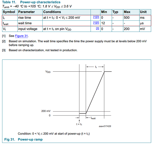
Figure 1 Power on request
From Figure 1, we can see that the chip input power from the 200mV below the starting point to rise to VDD tr, manual requirements can not exceed 500ms. The large capacitance in the circuit and even the super capacitor obviously will greatly increase the power-on time. For a power supply design without detailed parameters, this time may even be more than 500ms. In this case, the power-on time requirement of the chip cannot be satisfactorily satisfied, resulting in the system being unable to start, or the problem of device latch-up caused by the disordered power-up sequence within the device.
Therefore, slow power-on of the power supply is sometimes a “headache†problem for MCU processors. How to effectively solve the problem of slow power-up? Don't worry about it. Let's talk about the problem of slow system power-down. And the problems caused by slow power-down are more common than the problem of long power-up time.
2. Start failure caused by slow power-down
In fact, there is a crucial parameter in the above-mentioned electrocardiogram, it is twait in the picture. We can see from the figure that the minimum value of twait is 12μs. The meaning of this parameter is that, before powering on, the chip's input power needs to be kept below 200mV for at least 12μs. This parameter requires our circuit to be powered back on. If the system needs to be powered back on, the chip's input supply voltage must be at least 200μs for at least 12μs. In other words, after the power is turned off, the power supply voltage of the MCU must be reduced to 200mV or less to be powered on again (12μs is very short and almost negligible), and the system can operate reliably.
Due to the large capacitance in the circuit, the system load is small, resulting in slow power down of the circuit. When we power on again, the power supply voltage of the chip may not yet fall below 200mV, as shown in Figure 2 below:
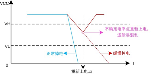
Figure 2 Slow Power-down and Power-up
Due to the large capacitance in the circuit, when the system load is not able to quickly discharge energy after the system is powered off, there will be slow power-down of digital devices such as the MCU. At this point, when the power is re-powered, the chip will not be “zeroed†in time because it does not meet the requirements of 12μs or more below 200mV mentioned above. For digital devices such as MCUs, this is an indeterminate state. At this time, when the system is re-powered, the logic of the MCU may be confusing. As a result, the device latches up and the system cannot start.
Slow power-down can also cause chaos in the power-down sequence of digital devices such as MCUs. Especially for MCUs that require multiple power supplies, they have higher requirements for power-up timing and power-down timing, and internal timing disruptions can cause The device latches and the system does not start. This is why the system often fails to start when many products are restarted.
Therefore, we can see that the slow power-up or power-down of the system may cause the MCU to fail to start up or start up abnormally. How do you intervene on the slow power-up and discharge process to increase the power-up slope and shorten the power-down time?
Second, the solution recommended
When you encounter the problem of system startup failure, please use the oscilloscope to check whether the power supply pin of the device is slow and the power-down is slow and incomplete. When encountering this situation, you can choose to use the small-sized, low-resistance power conditioning module developed by Guangzhou Ligong Monolithic Technology Co., Ltd. in the circuit: QOD-ADJ.
The module can ensure that when the system is powered on, when the voltage reaches about 70%-75% of the rated voltage, the output is turned on. Then the output follows the input, which is equivalent to a very fast power supply to the system. When the power is turned off, the module can automatically discharge the residual voltage of the capacitor and can reach 100mV or less in a very short time, thereby solving the problem that the system is in a locked state when the power is turned on again in a short time. The so-called power-on is correct! The system can be stable and reliable.
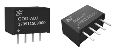
Figure 3 QOD-ADJ module
QOD-ADJ has the following functions: rapid power-on when the system power is on, boosting the power-on slope; rapid discharge of capacitive load to nearly 0V when the power is turned off; single-channel load switch that can be controlled externally; easy to use , Into the need to control the circuit can be.
Third, the use of products
Use the circuit shown in Figure 4 below to test our product:
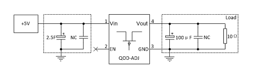
Figure 4 test circuit diagram
The power-on and power-down curves when VIN=5V, Cin=2.5F (supercapacitor), CL=100[mu]F, and RL=10[Omega] are shown in FIG. 5 and FIG. 6 shows the input 2.5F supercapacitor and load 10[Omega] power-down curves.
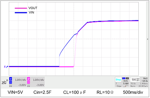
Figure 5: Input 2.5F supercapacitor and load 10Ω power curve
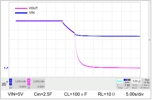
Figure 6 Input 2.5F supercapacitor and load 10Ω power off curve
1. Significantly reduced power-on time
It can be clearly seen from the above two diagrams that the VIN power-on curve (blue curve) climbs slowly because of the existence of a super capacitor, and after the module (Vout red curve), the power-on time is significantly shortened, so that the subsequent circuit can A certain state is reached in a short time.
2. Significantly accelerate power-down
It can be seen from the figure that when the system is powered off, due to the existence of a super capacitor, the front end (blue curve) of the module is slowed down, abnormally slow, and after passing through the module (red curve), the discharge speed can be significantly accelerated, making the subsequent circuit Get to a certain state in a very short time.
The devices in the system have strict requirements on the power supply and power on and off. In the product design, it is necessary to pay attention to the power-on and power-off requirements of the core devices, including the timing of power-on and power-off, and the slope, etc. Unreasonable designs often cause system power-on failure. Such abnormal conditions.
Kayak Seat & Boat Seat,High Quality Kayak Seat & Boat Seat,Kayak Seat & Boat Seat Details, CN
NINGBO MARINE OUTDOOR CO., LTD , http://www.marineoutdoors.com