The CA6140 model machine product belongs to a very typical product produced by Shenyang Machine Tool Co., Ltd., which was put into production in the 1970s. At that time, it was widely used in China's machinery manufacturing industry. The overall structure of the CA6140 model machine is very compact, its operating speed is relatively high, its operating efficiency is also very high, it has good precision and can realize digital control. CA6140 model machine has many advantages such as economy, high efficiency and environmental protection. Therefore, it is widely used in many fields, mainly used in the actual processing of some relatively complex shaft and disc parts. in.
1. Main drive system transformation design
1.1 Determination of the transmission form
In the case of a centralized drive: In the designed drive train, all drive configurations and shifting mechanisms are located in the same headstock. In the design process of medium-sized machine tools and large machine tools, it is more suitable to apply this type of transmission, especially for the CA6140 model machine equipment, because its overall structure is more compact, it is more conducive to centralized control, so that Effectively reduce production costs. However, when the transmission component is actually running, certain vibration and heat problems may occur, which may easily cause deformation of the spindle structure, which may eventually affect the machining accuracy of the workpiece.
1.2 Number of transmission pairs in the drive train and each drive train
In the design of the drive chain, the principle of the option is to ensure that it is as economical as possible while ensuring performance requirements. There are more than one design scheme that meets the requirements of machine tool equipment. In the process of designing the transmission chain, it is necessary to combine the design principle of economy to ensure that the design scheme is the optimal solution. By using the speed map, it is better to compare and analyze different schemes, and at the same time give some reference for the transmission system design. In the process of formulating the speed map, the specific steps are as follows.
Firstly, it is necessary to design a corresponding transmission scheme. In this scheme, the specific mode of the transmission and the opening and stopping operations of the machine tool should be clarified. The mode of reversing operation and the specific operation mode should also be clarified. The transmission form refers to the corresponding transmission and shifting forms according to the specific composition characteristics and structural characteristics of different conventional components and shifting components.
The design of the transmission scheme and the specific form will be greatly affected by the complexity of the system, and will also be affected by the performance requirements of the equipment. Therefore, in the design of the transmission scheme, it is necessary to consider the system structure, operation process and system performance in all aspects.
If the number of stages of the transmission system is Z, it contains different transmission groups, wherein the transmission pair is Z1, Z2, Z3, Z4, ..., then Z = Z1Z2Z3Z4.
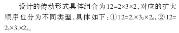
Because of the constraints of the overall structure, usually the number of transmission pairs is 2 or 3 is relatively suitable, that is, the corresponding shift series Z belongs to the 2 and 3 corresponding factors, which can be:
In order to achieve the goal of 12-level transmission, there are many different combinations of transmission pairs in the designed transmission system, as follows:
112 = 3 × 4, 212 = 4 × 3, 312 = 3 × 2 × 2, 412 = 2 × 3 × 2, 512 = 2 × 2 × 3, and the like. In the above form, if the first and second forms are used, one transmission shaft component can be saved, but four different transmission pairs are included in the same transmission group, if a quadruple sliding gear is used. Will cause the drive shaft size to increase further. If two two-slide gears are used, the design operating mechanism should be mutually pinned so that different slip gears can be prevented from engaging at the same time. Therefore, these two forms are usually not used.
If the third, fourth and fifth forms are adopted, the specific design process of the transmission pair is more suitable in the third form according to the principle of more before and after, but at this time, the I-axis is undergoing the commutation operation. The two-way type friction clutch device should be utilized, so that the axial length required for the I-axis can be relatively small, and the size of the transmission structure can be further reduced. However, because the number of transmission pairs included in the first transmission group should be less, it is suitable to select two transmission pairs. Therefore, the transmission form of this design is most suitable in the fourth form, namely 12=2×3×2.
1.3 Arrangement of the expansion sequence of the transmission system
If the first type is selected, the following specific problems exist.
In the case of the speed reduction transmission at the first shifting group, the size of the corresponding gear on the I-axis structure should be slightly larger because of the size limitation of the friction clutch device itself, and the corresponding gear size on the corresponding II-axis structure needs to be increased in multiples. This will cause the center distance between the I-axis and the II-axis to increase further, and the center-to-center distance between the I-axis and the II-axis will also increase, which will result in a relatively large system size. Therefore, from a practical point of view, This type is not easy to adopt. With the second type selected, the above problems can be solved.
1.4 Drawing the speed chart
The specific structure diagram of the designed main drive system speed of the lathe is shown in Figure 1.
Figure 1 speed structure network
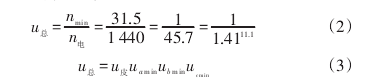
1.5 Distribution speed reduction ratio
In the process of designing the variable speed transmission process of the spindle component of the machine tool, the size of the driven gear component should be prevented from being too large, so that the corresponding size of the transmission structure is not excessively large, and the speed reduction transmission ratio is usually limited. It is required that the minimum value needs to satisfy Umin ≥ 1/4. In order to prevent the transmission error from further expanding and to ensure the noise is smaller, the maximum speed ratio is usually limited, and the maximum value is required to satisfy Umax ≤ 2, so the maximum shift range corresponding to the transmission group can be calculated as r ≤ umax / Umin=8.
In the CA6140 lathe, the spindle drive system consists of four different drive trains, one of which is a belt drive. According to the specific distribution requirements of the speed reduction ratio, it is necessary to meet the requirements of the previous slow speed and fast, and also meet the specific operating speed requirements of the friction clutch device to further calculate the minimum gear ratio corresponding to different transmission groups.
The CA6140 model lathe spindle drive system has a total of four drive trains, one of which is a belt drive. According to the principle of “pre-slow and fast†and the working speed requirement of the friction clutch, the minimum transmission ratio of each transmission group is determined according to the speed reduction ratio distribution.
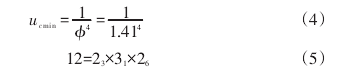
The total gear ratio in the system is:
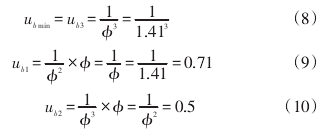
First, for determining the axis III axis and the IV axis, the corresponding minimum value of the down-speed transmission ratio should be larger than that of the gear component in the spindle structure, so that the flywheel function can be effectively utilized. Therefore, for the transmission group structure, the minimum value corresponding to the reduction gear ratio possessed by the transmission group should be selected as the limit value 1/4, and the corresponding common ratio is Φ=1.41, 1.414=4.
In the final stage, the specific interval is 6 levels.
Secondly, the intermediate shaft structure corresponds to the calculation of the transmission ratio, and the minimum transmission ratio can be further calculated according to the principle of fast and slow first, and the remaining transmission ratio is further calculated according to the basic index.
The transmission mode between the I and II axes belongs to the speed increasing transmission. The outer diameter value of the gear structure should be further increased to ensure that the diameter of the root of the driving wheel can be larger than the outer hub structure of the clutch device.
Therefore, it can be calculated that the corresponding gear ratio of the pulley is:
2, the choice of bearing
2.1 Bearing selection on general drive shaft
In the design process, the corresponding outer diameter of the transmission component in the designed I-axis structure is smaller than the diameter of the support hole structure at the left position, and all of them are
Deep Groove Ball Bearing components, which are hoped during the actual assembly process. It is more convenient and helps to better adjust the gap between the
Bearing Components. The bearing components used in the II-axis structure and the III-axis structure are all tapered roller bearing components.
2.2 Types of spindle bearings
For the spindle structure, in the process of designing the front bearing component, the selected bearing structure belongs to the double-row cylindrical roller bearing component, and there is a certain taper on the inner hole surface of the bearing, and this taper just corresponds to the spindle structure. The taper is matched with each other, and the movement occurring in the axial direction belongs to the inner ring. The author designs the inner ring structure to expand, which can effectively avoid the gap problem and the pre-tightening problem. The rolling element used in the bearing structure belongs to The roller can carry a larger radial load and also has a relatively high rotational speed value. In the bearing structure, a total of two rows of roller elements are arranged, and the arrangement form belongs to a cross form, and the number of roller elements is relatively large. Many, at the same time, have relatively good rigidity, and the temperature rise is relatively low, but because the bearing axial force is relatively poor, it should be applied in practice with a bearing structure that can carry a relatively large axial force. This also makes the design of the support components relatively complex.
3, the conclusion
In the comparison of the transmission system design of the CA6140 lathe and the general type of machine tool and CNC type machine tool, the transmission system components designed by the lathe can ensure the further expansion of the machining process range, and can also significantly reduce the machining time quota and ensure the lathe machining. The efficiency is further improved, and the different gear ratios can be ensured by means of the matching gears, so that the scope of the machine tool is further increased.
A linear-motion bearing or linear slide is a bearing designed to provide free motion in one direction. There are many different types of Linear Motion Bearings.
Motorized linear slides such as machine slides, XY tables, roller tables and some dovetail slides are bearings moved by drive mechanisms. Not all linear slides are motorized, and non-motorized dovetail slides, ball bearing slides and roller slides provide low-friction linear movement for equipment powered by inertia or by hand. All linear slides provide linear motion based on bearings, whether they are Ball Bearings , dovetail bearings, linear Roller Bearings, magnetic or fluid bearings. XY Tables, linear stages, machine slides and other advanced slides use linear motion bearings to provide movement along both X and Y multiple axis.
Linear Motion Bearings
Linear Motion Bearings,Linear Motion Ball Bearing,Motion Ball Bearing,Linear Guide Motion
Ningbo Ritbearing Imp & Exp Co.,Ltd. , https://www.nbbearing.de